
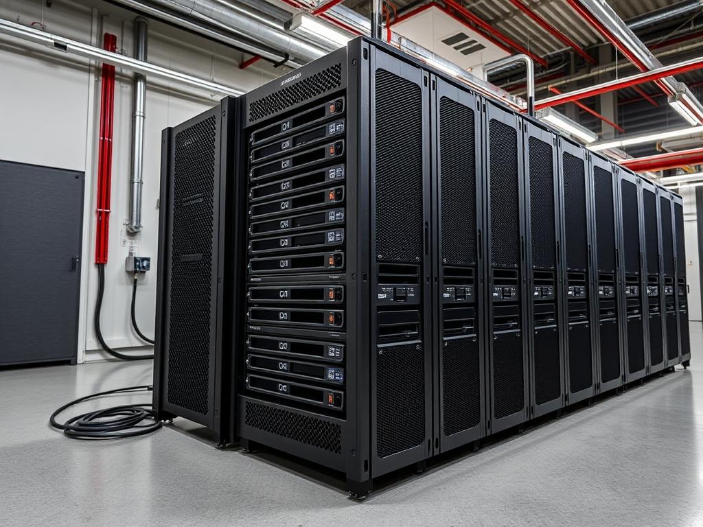
RAID 10 represents the synthesis of performance and reliability in modern enterprise storage. In the sphere of high-load data center infrastructure, such as clustered database environments or large-scale virtualization hosts, storage throughput often acts as the primary bottleneck. Traditional RAID levels like RAID 5 or RAID 6 introduce significant parity overhead, which increases write latency and complicates rebuild cycles. RAID 10 avoids parity calculations entirely by utilizing a nested architecture of striping and mirroring. This approach ensures that data availability remains constant even if multiple non-adjacent drives fail. The RAID 10 setup is particularly critical for infrastructure requiring high concurrency and low-latency response times, such as localized cache layers or transaction logs. By eliminating the write-hole phenomenon associated with parity-based arrays, RAID 10 provides an idempotent storage baseline that auditors and architects rely on for mission-critical payloads.
TECHNICAL SPECIFICATIONS
| Requirement | Port / Operating Range | Protocol / Standard | Impact Level | Recommended Resources |
| :— | :— | :— | :— | :— |
| Minimum Drive Count | 4 Physical Units | SAS-3 / NVMe Gen4 | 10 | 8-Core CPU / 16GB ECC RAM |
| Interface Standard | 12Gbps per channel | IEEE 802.3 / T10 SAS | 8 | Shielded Backplane |
| Controller Type | Hardware or Software | AHCI / NVMe / HBA | 9 | Dedicated RAID ASIC |
| Operating Temp | 10C – 35C (Inlet) | ASHRAE Class A1-A4 | 7 | Active Cooling (120mm+) |
| Vibration Tolerance| 0.5 G (5 – 500 Hz) | ISO 2631 | 6 | Anti-vibration Mounting |
THE CONFIGURATION PROTOCOL
Environment Prerequisites:
Deploying a reliable RAID 10 volume requires a foundation of uniform hardware. Ensure that all participating drives have matched capacities, spindle speeds, and firmware versions to prevent variance in throughput. The operating system must have the mdadm utility (v4.1 or higher) installed for software-defined arrays. For hardware RAID, the controller’s UEFI/BIOS must be updated to the latest vendor-specific microcode. Administratively, the user must possess sudo or root privileges to manipulate block devices. Ensure that smartmontools is installed to monitor drive health during the initialization phase, as signal-attenuation or physical media defects can cause immediate array degradation.
Section A: Implementation Logic:
The logic of RAID 10 is rooted in the “Stripe of Mirrors” design. Unlike RAID 01, which stripes data then mirrors the stripes, RAID 10 mirrors individual drives first. This structural hierarchy is essential for rebuild efficiency; when a drive fails, only its mirror partner is required for data restoration. This localized recovery process drastically reduces the window of vulnerability. By striping across these mirrored pairs, the system achieves a linear increase in read and write throughput relative to the number of mirrors. This configuration allows for maximum concurrency as I/O requests are distributed across all active spindles or flash channels.
Step-By-Step Execution
1. Drive Discovery and Integrity Verification
The first step involves identifying the specific block devices intended for the array. Use the command lsblk -o NAME,SIZE,TYPE,MODEL to list all available disks.
System Note: This action queries the kernel’s udev subsystem to report all recognized storage peripherals. It ensures that the architect does not inadvertently overwrite the system boot partition or existing data volumes.
2. Forensic Metadata Clearing
Before assembly, any existing filesystem signatures or RAID metadata must be purged using mdadm –zero-superblock /dev/sd[b-e]. Note that the device names must correspond to your specific identification from the previous step.
System Note: This command targets the start and end offsets of the physical disk where raid-specific headers reside. Clearing these ensures the array assembly is idempotent and prevents the kernel from misidentifying the disk based on legacy configurations.
3. Array Construction and Layout Selection
Construct the array using the command: mdadm –create –verbose /dev/md0 –level=10 –raid-devices=4 /dev/sdb1 /dev/sdc1 /dev/sdd1 /dev/sde1.
System Note: This initiates the RAID 10 kernel thread. The –level=10 flag triggers the md driver to implement the “near” layout by default; this layout places two copies of each data block on different drives at the same relative offset, optimizing seek times.
4. Synchronization Monitoring
Monitor the initial synchronization process by executing watch -n 1 cat /proc/mdstat. This provides a real-time view of the rebuild percentage and estimated time to completion.
System Note: During this phase, the system experiences high I/O overhead as data blocks are mirrored across the pairs. Thermal-inertia should be monitored closely; high-speed synchronization can cause rapid temperature spikes in dense drive cages.
5. Filesystem Encapsulation
Once the synchronization reaches a steady state, create a high-performance filesystem using mkfs.xfs -f /dev/md0. XFS is preferred for its ability to handle large concurrent data streams and its excellent metadata management.
System Note: The filesystem tools calculate the internal stripe width based on the RAID 10 geometry. This alignment ensures that data payloads do not span unnecessary block boundaries, which minimizes latency.
6. Persistence and Metadata Archiving
To ensure the array persists after a reboot, the configuration must be saved: mdadm –detail –scan | sudo tee -a /etc/mdadm/mdadm.conf. Follow this by updating the initramfs: update-initramfs -u.
System Note: Standard Linux boot sequences do not automatically detect software RAID arrays unless they are explicitly defined in the mdadm.conf file. Updating the initramfs ensures the array is assembled before the root filesystem is mounted.
Section B: Dependency Fault-Lines:
Software RAID 10 is susceptible to conflicts if the underlying drive controllers are set to “RAID Mode” instead of “AHCI” or “JBOD” in the system BIOS. This double-encapsulation causes unnecessary processing overhead and can mask drive failures from the OS. Additionally, mismatched drive sizes will result in the array being limited to the smallest drive’s capacity, creating wasted “ghost” space on larger units. Network-attached storage (NAS) deployments must also account for signal-attenuation in long SAS cables, which can manifest as intermittent drive drop-outs or packet-loss across the internal bus.
THE TROUBLESHOOTING MATRIX
Section C: Logs & Debugging:
When an array enters a degraded state, the primary diagnostic tool is mdadm –detail /dev/md0. This command provides a comprehensive breakdown of active, spare, and failed devices. Reviewing the kernel ring buffer via dmesg | grep -i raid often reveals the root cause of a failure; such as a “Timeout” or “Media error.” For physical fault detection, check /var/log/syslog for specific SCSI sense codes which indicate mechanical failure or electrical fluctuations. If a drive has been dropped from the array, but the hardware is verified as healthy, use mdadm –manage /dev/md0 –add /dev/sdX to re-integrate the disk and initiate a re-sync.
OPTIMIZATION & HARDENING
Performance Tuning:
To maximize throughput, adjust the read-ahead buffer for the RAID device. Use blockdev –setra 4096 /dev/md0. This increases the amount of data the kernel pre-loads into memory, significantly reducing latency during sequential read operations. For SSD-based RAID 10 arrays, ensure that the discard mount option is used in /etc/fstab to enable TRIM support; this maintains write speeds by managing cell degradation effectively.
Security Hardening:
Security in storage involves both data integrity and access control. Implement LUKS encryption on top of the RAID device before creating the filesystem: cryptsetup luksFormat /dev/md0. This ensures that even if individual physical drives are stolen, the data payload remains protected. Furthermore, set the mdadm.conf to send automated email alerts to the administrator upon any “DegradedArray” or “SparesMissing” events to minimize the mean time to recovery (MTTR).
Scaling Logic:
Expanding a RAID 10 array requires adding drives in pairs. While RAID 5 can be expanded drive-by-drive, RAID 10 requires the addition of a new mirrored set to the existing stripe. Use mdadm –grow –raid-devices=6 /dev/md0 –add /dev/sdf1 /dev/sdg1. After the array grows, the filesystem must be expanded using xfs_growfs /mnt/raid_volume. This scaling logic allows the infrastructure to grow linearly with the demand for higher IOPS and capacity.
THE ADMIN DESK
How many drive failures can RAID 10 survive?
RAID 10 can theoretically survive up to half the drives failing, provided that no two drives in the same mirrored pair fail simultaneously. If both drives in a single mirror fail, the entire volume’s data is lost permanently.
Why is my RAID 10 sync speed so slow?
Sync speeds are governed by the kernel limiters. To increase the speed, write higher values to /proc/sys/dev/raid/speed_limit_min and /proc/sys/dev/raid/speed_limit_max. Ensure your cooling system can handle the increased thermal-inertia of the drives.
Is RAID 10 better than RAID 6 for SSDs?
Yes. RAID 6 involves heavy parity calculations that result in “Write Amplification” on SSDs, shortening their lifespan. RAID 10 performs straightforward mirroring; this reduces the computational overhead and extends the longevity of the flash cells.
Can I use different drive sizes in RAID 10?
You can; however, the array will treat every drive as if it has the capacity of the smallest disk. This results in significant capacity loss on the larger disks and is generally considered an inefficient use of hardware resources.
What is the “near” versus “far” layout?
The “near” layout copies data blocks close to each other for standard performance. The “far” layout spreads copies across different sectors to improve sequential read performance; though it increases write latency significantly due to the increased distance for the drive heads.